
Data Center Waste Heat Recovery: The Complete Engineering Guide (2026)
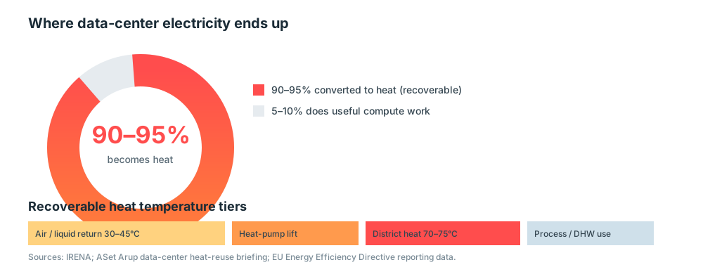
Data centers are on track to consume ~1,000 TWh of electricity per year by 2030 (IEA), up from roughly 103 GW of installed capacity today heading toward 200 GW. Almost none of that energy disappears: 90–95% of the electricity a data center draws is converted into heat. For decades that heat was simply rejected to the atmosphere. Today — driven by the AI build-out, rising energy prices, and binding European policy — data center waste heat recovery has moved from a nice-to-have to a design requirement and a revenue opportunity.
This guide explains how the recovery chain works, what the policy and economics look like in 2026, walks through the landmark Meta / Facebook Odense case, and links to the equipment and compliance details engineers actually search for.
Why data center heat recovery is suddenly urgent
- Scale: IRENA notes data-center electricity use rose more than 250% over five years (IEA, 2022). In Germany alone, data centers already convert 13 TWh/year into heat at 25–40°C — most of it wasted.
- Policy: The EU recast Energy Efficiency Directive (EU) 2023/1791, operationalized by Delegated Regulation (EU) 2024/1364 (in force June 2024), requires operators above 500 kW to report waste-heat utilization to a central EU database, and those above 1 MW to reuse waste heat or formally justify why not. Germany’s Energy Efficiency Act (EnEfG) goes further: facilities with ≥300 kW IT capacity must reuse 10% of waste heat by July 2026, 15% by 2027, and 20% by 2028. France (Decree 2025-1382) and the Netherlands have transposed similar duties.
- Economics: Recovered heat often lands at €18–35/MWh versus €70–80/MWh for natural gas — a direct hedge against volatile energy prices and a new off-take revenue line.
Where the energy goes (and how much is recoverable)
The chart below shows the unavoidable physics: nearly all delivered electricity becomes low-grade heat that can be captured.
The recovery chain has four stages:
- Capture — warm air from servers, or (increasingly) warm water from direct-to-chip liquid loops, at 30–45°C.
- Transfer — brazed-plate and shell-and-tube heat exchangers isolate the facility loop from the cooling loop without adding refrigerant circuits.
- Upgrade — a heat pump (often renewable-powered) lifts the temperature to 70–75°C, the range district heating networks require.
- Distribute — into municipal district heating, industrial process heat, greenhouses, or aquaculture.
Case study: Meta / Facebook Odense — 100,000 MWh per year
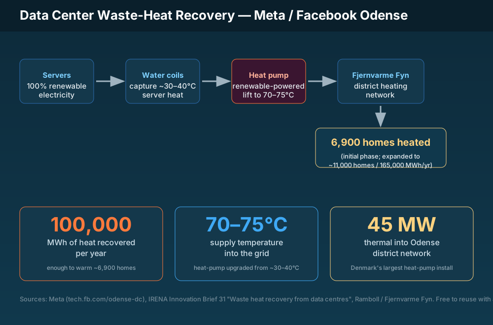
The clearest proof point is Meta’s Odense, Denmark data center, cited directly by IRENA Innovation Brief 31 (“Waste heat recovery from data centres”). The facility was deliberately sited next to the Fjernvarme Fyn district heating network and designed to donate its heat.
The numbers:
- 100,000 MWh/year of heat recovered in the initial phase — enough to warm ~6,900 homes.
- Server heat is drawn over water coils; a renewable-powered Bomba de calor lifts it to 70–75°C before it enters the district network.
- At full build-out the system delivers roughly 45 MW thermal into Odense and up to ~165,000 MWh/year, serving around 11,000 homes — among Denmark’s largest heat-pump installations.
Reuse this graphic: the infographic is published under a free-to-reuse-with-attribution license at 26yc.com/…/odense_infographic.svg. (Sources: Meta tech.fb.com/odense-dc, IRENA Innovation Brief 31, Ramboll / Fjernvarme Fyn.)
Equipment choices by recovery point
- Support / white-space ventilation: air-to-air rotary wheels and plate exchangers recover exhaust heat from offices, control rooms and break areas.
- IT load (air-cooled): capture heat in the air handler; upgrade with a heat pump.
- IT load (liquid-cooled): liquid cooling and immersion loops produce higher-grade 35–45°C water that is cheaper to upgrade — see the dedicated guide.
- Battery storage on site: co-located BESS thermal management both protects cells and can return its rejected heat to the same recovery loop.
Compliance you must design around
Beyond EU reporting, building codes increasingly mandate energy recovery by climate zone. In the U.S., ASHRAE 90.1 §6.5.6.1 triggers recovery above airflow thresholds that vary sharply by zone and outdoor-air fraction; California Title 24 y el EU Ecodesign rules add their own duties. Designing recovery in from day one is far cheaper than retrofitting.
Related reading
- Por qué los centros de datos apuestan por la recuperación de calor residual
- Data Center Heat Recovery with Rotary Wheels
- Heat Recovery in Data Centers: Air-to-Air Exchangers
- Recuperación de calor en los códigos energéticos: ASHRAE 90.1, IECC y mandatos EC
Bottom line
Waste heat recovery turns a data center from a pure energy sink into a neighborhood heat source. The technology is mature, the policy tailwind is binding, and reference projects like Odense prove the model at scale. The remaining constraint is almost always the local district heating network — which is exactly why early siting and off-take agreements now drive project bankability.
Especifique el intercambiador adecuado
Nuestros ingenieros dimensionan el núcleo según su caudal, temperatura y presupuesto de caída de presión, y seleccionan recuperación por placa, rotativa o caloduc según la aplicación. Lea la guía del intercambiador , o contáctenos para una especificación.
Productos relacionados
Recuperación por placa, rotativa o caloduc para HVAC y ventilación.
Núcleos estacionarios de gran superficie para aire y líquido.
Recuperación de energía de alta eficacia para grandes caudales.
Corrientes pasivas y totalmente separadas para aplicaciones limpias.